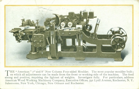
AMERICAN (ROWLEY and HERMANCE) NEW COLUMN 8″ MOULDER
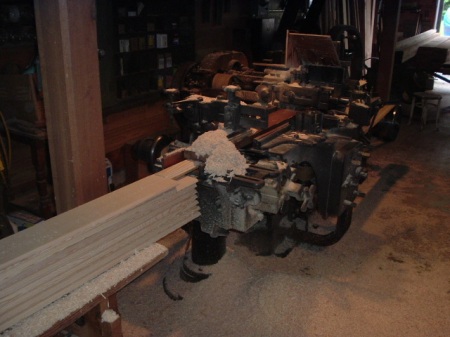
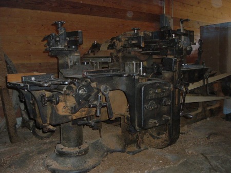
Distinctive for its rear column for support the out feed end of the table the New Column design by Rowley and Hermance became part of the American line. This is an outside moulder or sticker. The work passes outside the machine frame rather than through the center of it.
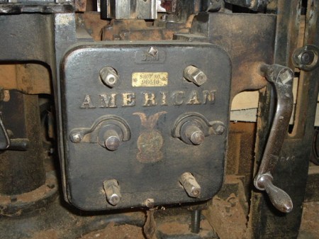
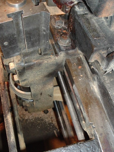
A distinctive Rowley and Hermance feature is the panel for adjusting the side heads. The inside head can be adjusted from the front as well as in back by means of threaded rods which pass through the machine to the spindle yoke. The rods can be mechanically linked so that once the tilt is established the spindle can be run in and out without altering the tilt angle. The elevation can also be altered without upsetting anything else.
The inside head rides with the bed.
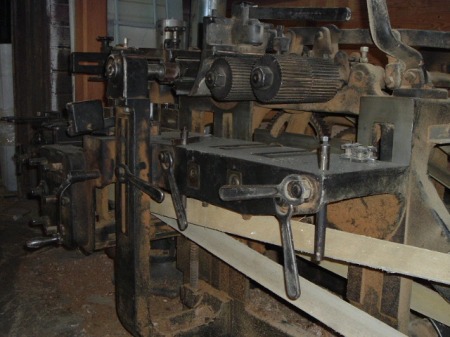
The feed is four powered rolls on a large canted “hinge”. This was a marked improvement over the Houston models I have, avoiding the rotation in the gear faces.
Heads are all running at around 4100 rpm. Side head belts twist left and right 90 degrees off the tailshaft for opposite rotation. The bottom head has a 180 degree twist to reverse direction. This is one of the three methods to reverse the bottom head. Another is to run the top head belt physically over the top of the bottom head belt at an intermediate pulley. This is the classic planer/matcher belting. The third is like on a tenoner. Rowley and Hermance used all three methods on its sash stickers and moulders.
The outside head belt can run quite slack depending on the bed height and the width of the material worked. Which is why I like leather on these. The inside head has a smaller range so the belt tension remains fairly consistent. The bottom head does slacken quite a bit when the bed is run low. But mostly, this machine is at about an inch in material thickness.
Most of the horse power is delivered to the top head for the heavy work. The top head has a belt tensioner. The development of the use of the lower head for profiling was a gradual evolution. On this machine, there is a moderate allowance for knife swing on the bottom head and the out feed bed swings down for easier access to the knives as opposed to swinging away to the side. Slip on heads can be used. This model allows a man to do heavy profiles on top and moderate to light below.
This is the distinctive R and H side head adjustment rods. The swinging fingers retain a hub in position to link the upper and lower rods. To tilt the heads, the finger is lifted out of it’s channel in the hub and the hub is pulled back and disengages allowing the rods to adjust top and bottom of the side head spindle yokes independently.
The bed rises with the crank shown. the same crank adjusts the side heads. the bed locks to the frame in three places. Bed rolls adjust for taper. I have them set to slightly climb the material to the fence and shoot it down to the bed just in front of the chip breaker.
This machine has served me well making cornice cap, base caps, picture rails, bed moulds, and small crown mould. It does a nice job on sidings doing the heavy work on the top head, rabbeting on the bottom and using low angle knives on the side heads.
Cutter spindle bearings are simple caps. They are set at angles to reduce pull to the gap but do not have the micrometer or wedge side clamping boxes of later moulders.
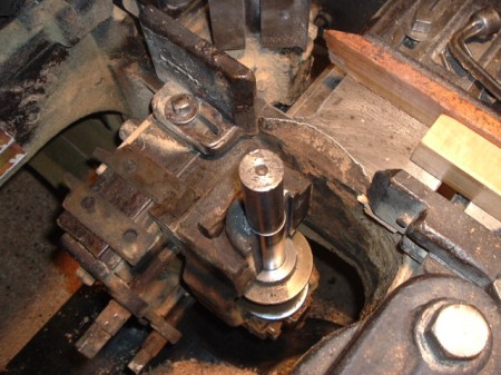
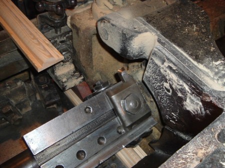
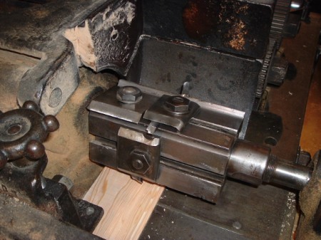
This is a look at the inside head spindle. I needed to get in here and adjust the bearings. the cap is off. The frame is behind spindle. An advance from earlier machines. The rods are the same as on the from so this head can be adjusted from either side of the machine.
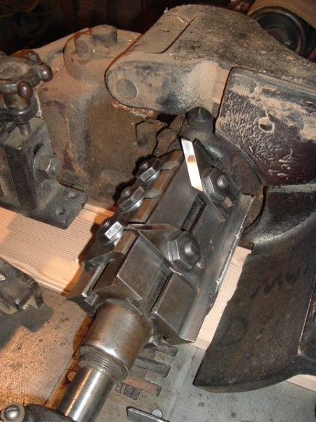
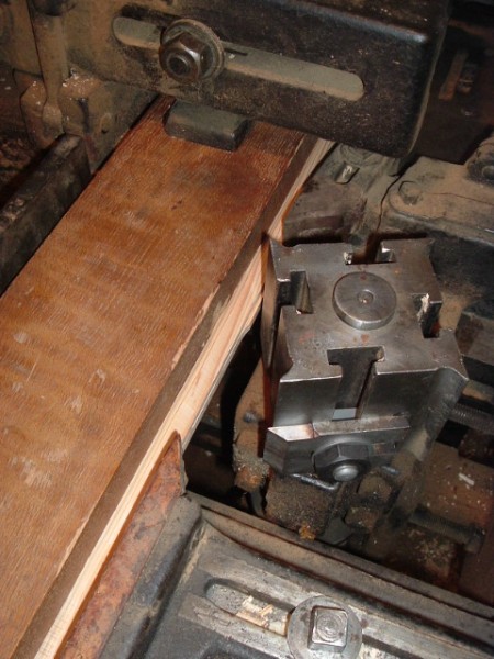
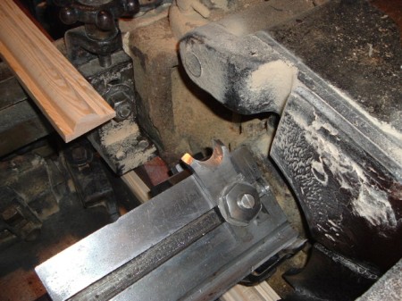
Here is the outside head and its adjustment rods. The pressure and chip breaker rides with the blocks onto which the joke elevates and swivels. The locks are under the bed. I general keep a little bite on these when adjusting to keep the slack out.
FIRST LINE SHAFT RUN
This is the first back to line shaft run after decades of electric motor drive. Siding.
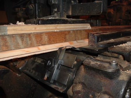
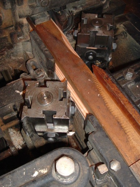
This is the top head. I am surfacing, sizing, rabbeting, and chamfering on this head.
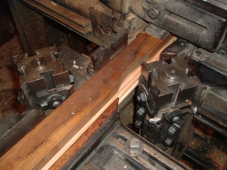
This is the outside head. I have sized the edge from above and this is just a small nibble to make the part uniform before we get to the bottom head.
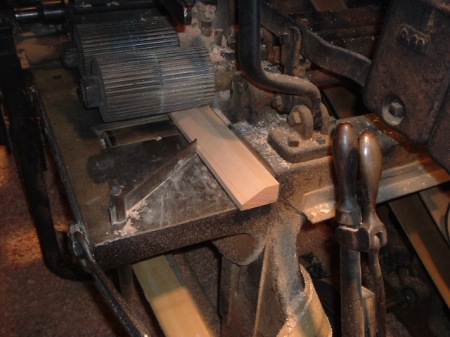
And here at the bottom the rabbeting. This pattern has a rough back so that’s all we do here. This pattern runs thicker than modern standard. In the old days, many matched products were run thicker and not surfaced four sides.
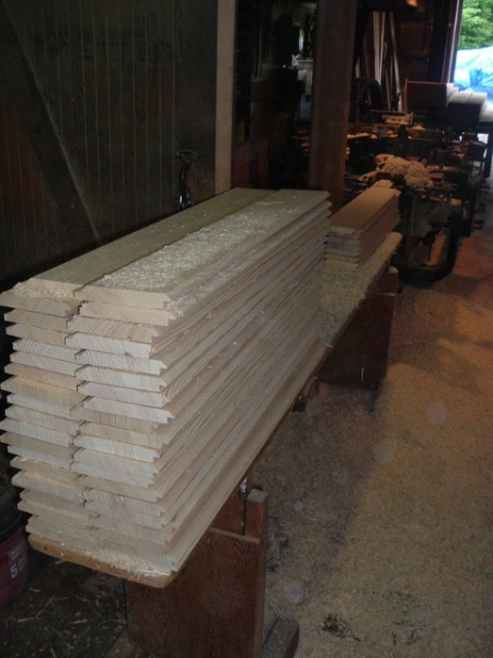
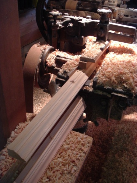
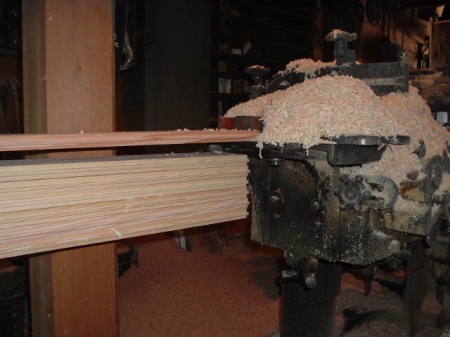
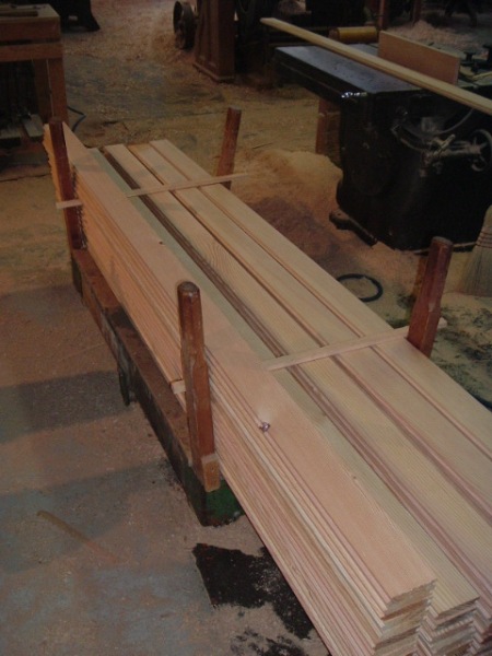
Always nice to see the parts pile up straight.
This next set of pictures shows a combination set up. The pattern is a special application band. This is the old way of doing variety work which is no longer recommended. But the concepts may have some interest to the modern mechanic.
The spikes and caps are balanced. The caps add mass to a balance center even though the knives are working opposite edges of the pattern. Notice the half round knife somewhat swaged. The ripples in the cut are from a loose pressure bar. Start loose then come down just short of stalling the feed.
No we will run run with the high side to solid guide which is best. This is a base cap. The bead is the high side so we run it to the guide. The bead and it’s balance are slotted. This knife also makes a picture rail. The balance is a panel mould knife.
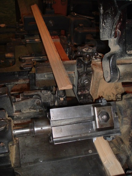
This bead knife is a spike. It gives us a bead, chamfer, and a fillet.
And its balance is an ogee knife. Be careful making adjustments when running close to the bed.
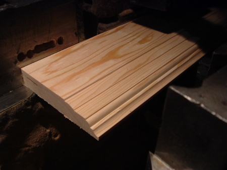
And one two three base cap. As you can see a many faceted profile created with simple components. This is key to understanding the Victorian Era profiles.
Crisp detail possible with spikes. I am not quite happy with this. Notice the difference between the spike finish and the wide flat.
The set up for the casing above.
Too much heel on the knives. I was lazy and pulled these from the cabinet without a fresh up. So now I give them a few minutes on the grinder, slip, and strop and back to work. The flat on the bead I worked down in place with a stone. In fir, heel will raise the grain fast. Vertical grain hides knife issues better than flat. Flat kind of tells all.
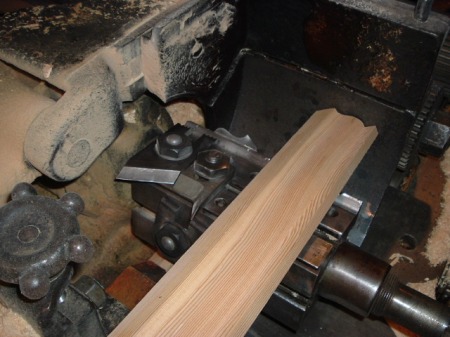
This is a bed mold set up. I use the top when the order only calls for a small footage. The chip breaker has had a new shoe put on it. For years the machine was running narrow stock and the foot ob the chip breaker was uneven with wear. So I had it trued and added a tool steel shoe. Another change was to reverse the bed plate. The next improvement will be to go to an endless top head belt.
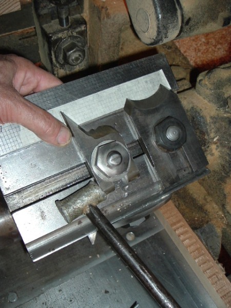
When small adjustments are needed, this is how I do it. trace the knives onto a piece of masking tape on the rule. Then I have a reference when I move the knife. the hammer is lead. The bolt is loosened slightly, the re-tightened after adjustment.
The other thing I do here is to split the work of the knife pairs. This will break up the chip. Powder on the knife back tells which is doing what part of the cut. I use the tape to show me how to alter one or the other to make a a blend and split the chip. I use to try to ride them the same but I now like to split the chip.
This is an old style crown mould set up. Combination. Knives shown are balanced by the same on opposite sides unseen. The rise/run on this rake mould is 3:2. So that means that any angle 3:2 on the grid of the sticker man’s rule will have an easy to locate complement using 2:3 on the rule. Forget the protractor and bevel gauges.
This is a cap mold. It is a heavy bite as you can see.
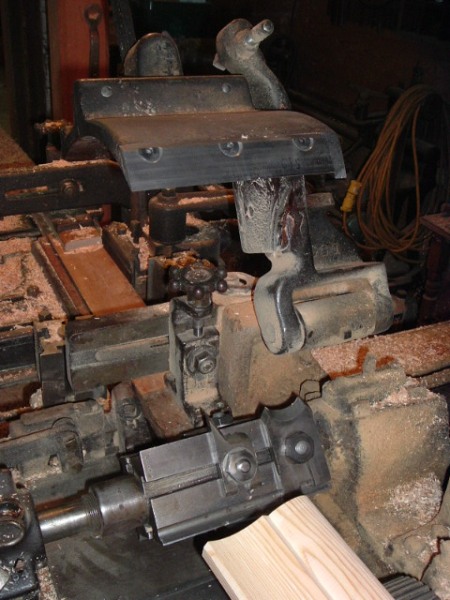
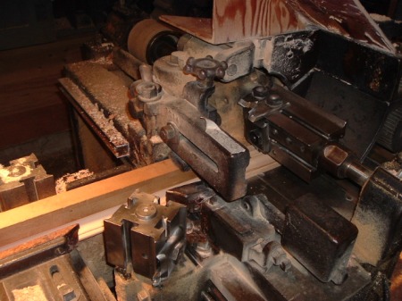
This is the set up. Top and outside heads.
I face and joint stock for caps. Twist or bow is hard on the end user.
To improve the finish and keep a keen edge on my knives longer, I take a slice off the blanks on the saw. The material as fed to the machine.
This is matching. Best done on matchers but frequently done on moulders. The tongue is run on the outside, the groove on the inside.
The groove is split between two knives, upper and lower. Lessens heat and divides the chip. One head will always be against the grain.
Matching flooring can be particular. It has to be right or the floor will lay hard and creak.
Knots need to be punched out before running. Afterwards the material needs to be handled carefully to protect the tongue. Sap side up (face) always to prevent raised grain.
CURVED MOULDINGS
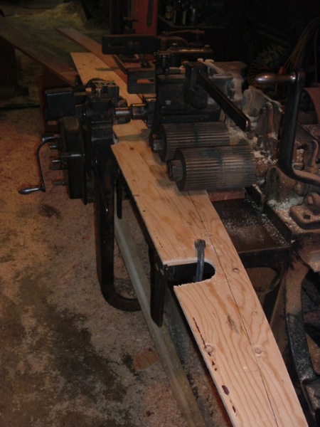
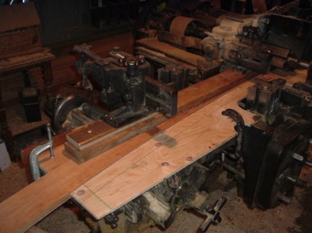
When curves are needed, it is possible to run segments through the molder with the same set up for straight work when using top head only. This is the wood guide against which the feed rolls will drive the segment under the knives.
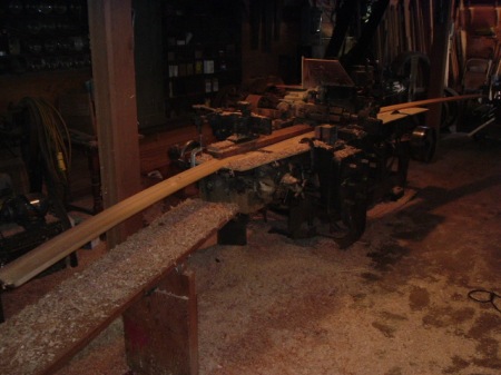
This is the out feed end. The part feeds nice. I am checking the set up without powering the top head.
Here is the 4 1/2″ bed mould segments going through the machine. I am lazy and use a flat pressure bar askew to ride the high points of the profile for this short run of 25′ radius stock. The part in this case is a rake mould that bends around a turreted porch.
OPERATING TIPS
Here are a few observations.
A slight loss of power is an indicator. It can be heard. Shut her down and turn the machine by hand just to check the spindles. Then attend to the drive belts. A small tear will reduce horse power. It is better to find the tear before it all gives at once and might get tangled. Wood split pulleys will spin on the shafting at the end of a dry spell.
When side head knife bolts are re-torqued or a knife is removed and replaced, it is possible to slightly alter the position of the vertical spindles. Direct leverage downward if possible.
Be strategic with knife bolt leverage to prevent then spindles from rotating while tightening.
Keep wax at hand to wax over pitch before entering the machine.
When the guides seem tight, loosen and re tighten them. Do not move them. The compressed fiber will move them for you. It will be imperceptible. Except in allowing the feed to smooth out.
Run the inside guides slack.
Elevate the material as it enters the feed rolls.
MOVIE DEPARTMENT
Postcard image of my machine.
Leave a comment